• Which the release of FS2020 we see an explosition of activity on the forun and of course we are very happy to see this. But having all questions about FS2020 in one forum becomes a bit messy. So therefore we would like to ask you all to use the following guidelines when posting your questions:

    • Tag FS2020 specific questions with the MSFS2020 tag.
    • Questions about making 3D assets can be posted in the 3D asset design forum. Either post them in the subforum of the modelling tool you use or in the general forum if they are general.
    • Questions about aircraft design can be posted in the Aircraft design forum
    • Questions about airport design can be posted in the FS2020 airport design forum. Once airport development tools have been updated for FS2020 you can post tool speciifc questions in the subforums of those tools as well of course.
    • Questions about terrain design can be posted in the FS2020 terrain design forum.
    • Questions about SimConnect can be posted in the SimConnect forum.

    Any other question that is not specific to an aspect of development or tool can be posted in the General chat forum.

    By following these guidelines we make sure that the forums remain easy to read for everybody and also that the right people can find your post to answer it.

MSFS Everything about CGL generation [Custom DEM works]

Messages
15
Country
finland
Hi Andy :)

I am not SprightlyOldMan, but Breadeater/morko. Only mods I've released so far are for Finland. Both are at flightsim.to.

Yes, you are absolutely correct. The documentation is lacking very much behind, as is the whole repository. Currently I leave the offset to 0 and add wgs84->egm2008 undulation to the source data (this of course assumes the elevation source data is relative to wgs84 ellipsoid). I'm sorry if I use wrong terms, I've yet much to learn. The area of geodesy seems really fascinating, and absolutely worth making careers of.

It's wrong to say it is limited to 20 meter GSD, because it depends on the latitude. The game uses data split to bing maps tiles and currently we can load from disk only level 6 tiles, which each can contain maximum of 6 "sublevels" (only true for dem-cgl, for example aerial image cgls can have 14 sublevels). 6+6=12 and on the equator bing maps tile level 12 GSD is about 40 meters.

E: it is not known that in game elevations are egm2008, it just seems to produce good results. Lots of guesswork going on :D
Regards
Teemu
 
Last edited:
Messages
7,450
Country
us-illinois
Great questions, I can't answer this for sure until there is more information in the SDK on terrain.

From what I can tell, FS converts to WGS84 internally like a virtual globe. The Bing photogrammetry ships already in WGS84 coordinates, and the Bing DEM is also in relation the the WGS84 ellipsiod reference height.

Unlike FSX which just assumed the WGS84 ellipsoid for ground height, MSFS ships with a egm2008 undulations. Therefore the actual ground elevation will actually vary geographically, and which will catch you by surprise as a delta from the WGS height.

In terms of projecting QMID or raw sources to spherical mercator, that is an interesting point and I haven't wrapped my head around it yet. Maybe there is something in ESRI's tools that can help.

Hello spritelyoldman (a.k.a. Breadeater?),

I was looking at your ItalyDEM, which is excellent work and a pleasure to see! :) Many thanks indeed for making this available to the community! 👍👍

I was reading your documentation on GitHub. You wrote "Game height 0 is -16 meters relative to MSL" (which tallies with your instruction 2, above, namely "Correct elevation data to egm2008"), which I believe is an oversimplification of some really complex geodesy. A delta of 16m may work in some locations, but not others. It also depends on the geoid/ellipsoid and vertical datum of the source DEM. There is a lot of nuance and detail in this (hence entire textbooks and careers devoted to the topic), which I believe Asobo are also getting wrong in some places (I sense they could do with having an experienced geodesist on their team).

Also, why is the process [currently] limited to a GSD of 20m?

Many thanks indeed

Andy (a.k.a SpatialProf/Airtropper, depending on the site)

Indeed, it would be helpful for the FS Developer Community to have access to more detailed info from MS / Asobo and/or Sean Isom as to how EGM2008 is implemented In MSFS-2020 as a "correction" for EPSG:4326 source data with regard to creating custom *.CGL files. :banghead:

GaryGB
 
Messages
284
Country
us-newyork
Lol, oh boy. I will preface everything I am about to say with a huge disclaimer that the Terrain system in MSFS is completely undocumented, not easy to reverse engineer, and ever changing, and is not a current focus area for the SDK (which is really coming together in other areas). So take this as an educated guess compared to the FSX+ system which between texture synthesis, raster, and vector formats we have more or less completely figured out.

The primary elevation system in MSFS is provided by Bing Maps as Windows HDPhoto single channel heightmaps. These are stored in a quantized, nonlinear format. I'll publish the algorithm for this with the other TIN and Bing DEM stuff in my git repo shortly.

The DEM files on disk are a completely different data source and I know less about them (CGL Markers, vs Bing d0 tiles), but they are laid out on the same bing maps web mercator quadtree. As indicated in Breadeater's repo they are also stored delta quantized, but linearly in 16 bit from a base value.

Both appear to be triangulated on the CPU in double precision, not too differently from FSX (very different from P3D which is tessellated), so it is very difficult, in the absence of external SDK tools, to determine how exactly the two different types of data (bing vs cgl) are processed and interact with each other. What I can tell is that the tiles are rendered in WGS coordinates with offsets from a somewhat common local datum of within ~30km (shared between groups of tiles in the scene but not the entire scene).

With that background info, here is where I "think" undulations come into play. In FSX-P3D, the WGS84 reference ellipsoid is all that exists: there are no undulations. Heightmaps in the FSX system are raw altitudes from the reference ellipsoid, which is also "considered" ground level, and that is it.

In MSFS, there are other data sources that already ship in raw WGS84 like TIN data. So this means that "ground level" as considered by sims like FSX will no longer will match the "rendered ground level" here as the lidar data is already in raw WGS84 positions, like a GPS. So to "reverse" the actual MSL ground level from this kind of WGS visual ground level you have to apply the undulation.

How does this apply to terrain design? There are two possibilities, #1 is much more likely than #2, but I am not yet able to confirm:

1. Some data providers ship height data already "undulated" from GPS positions to egm96 or egm2008 offsets, meaning height above sea level, while some do not, meaning gps reference ellipsoid height. This means an identical data source from FSX would need the inverse applied for MSFS. For example, if you had data that was already egm2008 undulated in FSX, you would need to undo those undulations to see the same visual picture above the actual water in MSFS.
2. There is an egm2008 BIL files that's 56mb that ships in the core game directory for MSFS. It is possible that it is applying this to DEM data sources. However, I don't think this is likely, as I have worked with Azure / Bing tiles before, and I know no undulations are necessary as it seamlessly meshes with their TIN data, so it would seem unlikely to use a different system for just the CGL files. Furthermore this is low enough resolution that it wouldn't be super useful for this kind of task. I suspect it is used for other aspects of the game, like rendering 2D vector effects on TIN, or perhaps for even determining your AGL.

I hope that helps! This is going to be a long learning process for all of us.
 
Last edited:
Messages
7,450
Country
us-illinois
Many thanks, Sean, for this informative update on the MSFS-2020 Terrain 'learning process'. :)

GaryGB
 
Messages
59
Country
switzerland
Inspired by the suggestion to feed the heightmaps (which at first seemed a bit useless to me) with generated elevation data I did some experimenting in dev-mode first. I made some observations which I don't quite understand yet, but I guess some of you are more knowledgeable and can shed some light.

Hypothesis from my observations: There seem to be 3 layers of terrain data (my names):
  1. "Wireframe" (finest, ~1m max resolution): What you see when you switch to "wireframe" view. So it's likely the resolution that is renderered. I couldn't find a graphics setting to alter this resolution, even though this would probably be very relevant to performance.
  2. "target mesh" (~6m max resolution): Seems to be the finest resolution for elevation data. Features in higher resolution height maps don't show up in the rendering of the ground. With the setting "ground > only lighting" you can see facets with the ~6m resolution. So the wireframe seems to be interpolated (and slightly smoothed at the edges) from the target mesh. Again, there seems to be no graphics-setting to alter the resolution of this layer.
  3. "source mesh" (resolution determined by available bing/CGL-Data AND the graphics setting "Terrain Level of Detail"): When I change the Terrain LOD-setting to minimum, the hills around my airfield go flat, but my heightmap still has the 6m resolution.
Processing goes "source mesh" --> "target mesh" --> "wireframe". Terraforming tools can inject alternative data at the "source mesh" level.
  • Is the resolution of the "target mesh" always fixed at ~6m or can it be changed?
  • If the Terrain LOD-setting only affected the source mesh its impact on performance should be minimal. Yet, it affects frame rates at about 10% from the maximum to the minimum setting. Not that much, but still: why?
Thanks for any insight.
 

Attachments

  • heightmap-6m facets.jpg
    heightmap-6m facets.jpg
    316.6 KB · Views: 406
  • superimposed high resolution height map.jpg
    superimposed high resolution height map.jpg
    351.6 KB · Views: 417
Messages
284
Country
us-newyork
"Wireframe" (finest, ~1m max resolution): What you see when you switch to "wireframe" view. So it's likely the resolution that is renderered. I couldn't find a graphics setting to alter this resolution, even though this would probably be very relevant to performance.
This is from the dev mode tools for terraforming? Perhaps the grid lines here are at the 256X256 tile resolution for the max CGL dem level (20?). It is not totally apparent to me how the terraforming system works and blends with the cgl dem and bing dem markers. Anyways, if you want to see in real wireframe what the game is rendering, turn on wireframe in the dev mode debug view menus and you can see the tessellated terrain.

I think to answer your other questions we'll have to figure out how the terraforming markers work. I would be surprised if the "6m" globally upsampled to be rendered at "1m", that's would be a huge waste of triangles.
 
Messages
59
Country
switzerland
Ah yes, what you see on the screenshot is the effects of a heightmap with 1m spacing (to roughly match the wireframe spacing). As you can see, it can only affect the ground with a roughly 6m resolution.

I would be surprised if the "6m" globally upsampled to be rendered at "1m", that's would be a huge waste of triangles.

I wonder if the wireframe resolution only exists on the graphics card (mesh interpolation and smoothing with vertex shaders - is that a thing?)
 
Messages
59
Country
switzerland
Hi Breadeater

I wanted to try and start unterstanding CGL and had a brief look at your Code/Documentation. I have no idea how you figured out the laplace pyramid thing 👏
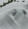
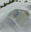
. Do you know more details about the properties of the pyramid? How does MSFS reconstruct the data?
* For instance, how do you know how much to blur when downsampling? Assuming that the pyramid levels translate 1:1 into mesh LODs my naive guess would be, that there should be no blurring at all, rather the opposite. Otherwise you would be unnecessarily losing detail in all LODs apart from the highest one (which coincidentally is a complaint people have with the ItalyDEM-scenery).
* Inversely, upsampling for reconstruction or generating the difference layers would have to be done exactly the same way MSFS does - otherwise there would be artefacts. The way pyrUp does it is possibly a bit too sophisticated, it might just be bilinear or even nearest neighbour. ItalyDEM has a known issue "Peak elevations might have small "spikes"" --> Artefact?
 
Messages
59
Country
switzerland
Hello
As this thread has come to a bit of a halt I might as well show my most recent findings. In my post above I was sceptical if the pyramid thingy as implemented in the openCV library used by breadeader/Mörkö is the right way to go - as the lower LODs get blurred (i.e. rounded in mesh terms). With a high quality mesh looking good from up close you end up with rounded/flattened peaks from a distance.

I took the swiss tile out of the ItalyDEM scenery by sprightly-old-man and re-downsampled the lower LODs using a simple average function. This is a common/easy method but not necessarily the best/least error - with a bit more effort there could be some more improvements.

So, we'll be comparing a view of the alps from above Zürich:
1. Default MS Scenery (looks a bit rounded even from a distance and is much too soft from up close)
2. ItalyDEM (looks too flat from a distance but looks much better than default scenery up close - I don't have a screenshot up close, so if you don't know the scenery you'll just have to believe me).
3. ItalyDEM re-downsampled (looks the same as ItalyDEM up close but preserves the spikyness from a distance)

20210415214057_1.jpg


20210415204918_1.jpg


20210415210048_1.jpg


The difference is already quite visible just with the peaks in the background. But we can also have a closer look at a little spike more in the foreground (Mythen). Once from a distance, once closeup:
1618521693356.png


I think, this shows that until your area is covered by a world update it might still be worthwile creating your own mesh.

Further work:
- iron out some artefacts
- implement a way to import external DEM data
- go beyond the 40m LOD?
 
Messages
284
Country
us-newyork
Hi,

This is certainly some good progress! Unfortunately in many major builds Asobo seems to evolve the architecture of the terrain engine, so without SDK support, it is difficult to continue the "hacking" and research in the face of uncertainty.

I agree that when downsampling you would probably get a better result from an average. The problem with a repeated gaussian like in the laplacian is that it will lead to an eventual dilation of the image. You can see this in the opencv docs on the subject: https://opencv-python-tutroals.read...rials/py_imgproc/py_pyramids/py_pyramids.html - in the edge detection version of the image, at lower resolutions the lines maintain their thickness, and even expand it in terms of number of pixels. This is desirable in image recognition algorithms under opencv to preserve detail at lower resolutions (else with enough erosion you'd end up with essentially a blank black image), however for terrain this leads to notable smoothing / lumps. The simple average will preserve the detail over a smaller area than a blur.

The most accurate way to downsample terrain is to use a geometric algorithm vs an image processing algorithm. P3D/FSX and most other virtual globe software over the years tend to use techniques like Chunked LOD (Ulrich, 2002) based on Restricted Quadtree Triangulation (Pajarola, 1998) for meshing. I wont restate the algorithms here, the original papers or others online can probably explain it better than I can, but the idea is that given a desired maximum geometric error, you calculate an activation level of each vertex on a heightmap, and while recursively iterating edge subdivisions calculate whether a vertex is necessary given the geometric error. This allows each lower LOD level to progressively remove detail in a way that is guaranteed to never vary visually past a certain rate, and when combined with runtime "Chunk" (LOD) selection by projecting the geometric error to screen space to figure out by how many pixels the model would vary can allow for a fairly seamless mesh refinement.

The best article I've found explaining this process is from Intel here: https://software.intel.com/content/www/us/en/develop/articles/terrain-rendering.html. They have since taken the sample offline, but I've put it up on GitHub here: https://github.com/seanisom/TerrainPack . Unfortunately you're going to need VS2010 to build it, it's ancient code, but I've ported the core logic to several different applications relatively easily over the years with newer releases of TBB.
 
Last edited:
Messages
59
Country
switzerland
Hi Sean

About the moving target: I get the impression that Asobo has such a large heap of technical dept piled up following the somewhat rushed release of FS2020 that things are moving really quite sedately now. I'm not sure we will see SDK support for mesh generation soon. And anyway, I'm just a hobbyist so it's a recreational activity - if it turns out to be of no use, so what.

Thanks for the info about chunked LOD - I'll have to have a closer look at it. I'm not quite sure yet how minimal error downsampling ties in with elimination of unnecessary lods yet. So far I've seen it as two separate steps.

To illustrate I add a rough diagram of what I'm doing:

Arch.png

Green arrows are transitions/algorithms that I have in some form.
- Elimination of unnecessary lods is what I have planned in the "prune/optimize" step. Discard differential tiles with neglectable amplitudes starting at the leaves. The MSFS default offline data seems to do that as well, as many CGLs have less that 341 tiles (5 Lods: 1+4+16+64+256). I guess this would become more interesting once we can get to higher LODs. At the moment it's probably mostly used for large water surfaces.
- (Re-)downsample LODs: As stated before, it's a simple decimation at the moment. Could get more sophisticated.
- Diff/apply diff: When starting to generate test data I noticed that I have some artefacts - probably because I use bilinear upsampling in the diff-steps. I'm currently working on a bicubic algorithm to see whether that improves things.
- As can be seen I have no way of importing DEM data yet (GeoTiff or something?). That's why I've used the ItalyDEM, as I have all the steps for a CGL to CGL roundtrip.

Andi
 
Messages
214
Country
unitedkingdom
The most accurate way to downsample terrain is to use a geometric algorithm vs an image processing algorithm. P3D/FSX and most other virtual globe software over the years tend to use techniques like Chunked LOD (Ulrich, 2002) based on Restricted Quadtree Triangulation (Pajarola, 1998) for meshing.

It is such a pleasure to see someone citing their sources (and in the correct format too)! 👍 👍 :)
 
Messages
59
Country
switzerland
So, I'm still experimenting with the CGL creation - haven't jumped onto the "plaster whole countries with heightmaps" bandwagon just yet. I finally managed to get the official (open data) swiss terrain model into my program - and then discovered some odd behaviour of FS:
I would expect FS to select the data source which provides the highest LOD for a given area and then stick with that source for all LODs. Yet, for large parts of western switzerland (close to the french border) the CGL source is used for the lower LODs where closeup it switches to the LOD(s) streamed from the cloud. This is very visible because the streamed mesh might have a nominally higher LOD but the mesh quality is still appalling (like the rest of switzerland). So the effect is that when getting closer, the terrain loses detail.

20210522193900_1.jpg

"Creux du van" at the highest LOD provided by local CGL file.

20210522193906_1.jpg

Closing in a bit

Is there anyone still trying to cross the border to the higher LODs? Or has even managed it?
 

Attachments

  • 20210522193900_1.jpg
    20210522193900_1.jpg
    679.1 KB · Views: 141
Messages
15
Country
finland
Yes, going beyond lvl12 is possible, only needs minor changes to the code.
level14.jpg

Level 14 dem showing good details
Also, as Sean and you discussed before, the laplacian pyramid way is wrong, it only resulted in somewhat OK results up close because it blurs the upper levels so much that the details of how the game does the mesh interpolation only cause some errors.

I think I figured out how the game actually creates it's mesh based of the CGL data:
First layer in the cgl is loaded as mesh vertice elevation "as-is".
Before adding next layer, the previous mesh is subdivided:
vert.png

Black edges are from the first layer mesh.
First the center vertex is calculated as average of the base vertices (9.375), this gives the red edges.
Then the other ends of green edges are calculated as an average of their connected neighboring vertices.
To that subdivided mesh the "delta" elevation values are added.
After all levels in cgl are used, a visual filtering can be applied if the player comes closer, based on a step response test, it looks like Lanczos, it can be added multiple times.

Mimicking that while building a delta tree from floating poing tree, results in very good detail and accuracy.

In other news:
Vegetation mask (VGM) format is solved and can be used to mask and set tree heights.
Vector data (VEC/VECN) is mostly solved. Road features work, with bridges and classification, "connectedness" is still WIP. Water polygons work 100 % (including holes and elevation). Other basic features should not take too much more effort (rivers etc). Conversion from shapefiles works well.
road.jpg

Custom road with a bridge

wmask.jpg

High resolution water

Regarding files available only from the cloud, a proxy software that can be used to feed custom data to the game works, with minor issues on the apps logic. Can be used for example to serve aerial images as jpg tiles, vegetation masks, color correction data, texture synthesis masks, etc. to the game.
vgm_aerial_road.jpg

Vegetation mask and aerial images fed to the game with a proxy application

So, a lot has happened, but reporting progress and documenting it is much behind :(
No promises when, but I'll get to it eventually.
 
Messages
34
Country
taiwan
Yes, going beyond lvl12 is possible, only needs minor changes to the code.
View attachment 73454
Level 14 dem showing good details
Also, as Sean and you discussed before, the laplacian pyramid way is wrong, it only resulted in somewhat OK results up close because it blurs the upper levels so much that the details of how the game does the mesh interpolation only cause some errors.

I think I figured out how the game actually creates it's mesh based of the CGL data:
First layer in the cgl is loaded as mesh vertice elevation "as-is".
Before adding next layer, the previous mesh is subdivided:
View attachment 73452
Black edges are from the first layer mesh.
First the center vertex is calculated as average of the base vertices (9.375), this gives the red edges.
Then the other ends of green edges are calculated as an average of their connected neighboring vertices.
To that subdivided mesh the "delta" elevation values are added.
After all levels in cgl are used, a visual filtering can be applied if the player comes closer, based on a step response test, it looks like Lanczos, it can be added multiple times.

Mimicking that while building a delta tree from floating poing tree, results in very good detail and accuracy.

In other news:
Vegetation mask (VGM) format is solved and can be used to mask and set tree heights.
Vector data (VEC/VECN) is mostly solved. Road features work, with bridges and classification, "connectedness" is still WIP. Water polygons work 100 % (including holes and elevation). Other basic features should not take too much more effort (rivers etc). Conversion from shapefiles works well.
View attachment 73456
Custom road with a bridge

View attachment 73457
High resolution water

Regarding files available only from the cloud, a proxy software that can be used to feed custom data to the game works, with minor issues on the apps logic. Can be used for example to serve aerial images as jpg tiles, vegetation masks, color correction data, texture synthesis masks, etc. to the game.
View attachment 73455
Vegetation mask and aerial images fed to the game with a proxy application

So, a lot has happened, but reporting progress and documenting it is much behind :(
No promises when, but I'll get to it eventually.
It is good to see such progress! Just want to verify do you mean it is possible to edit water mask under current structure? Trying to make some missing coral reef back to life. (Needs Aerial + updating water mask)
 
Messages
15
Country
finland
It is good to see such progress! Just want to verify do you mean it is possible to edit water mask under current structure? Trying to make some missing coral reef back to life. (Needs Aerial + updating water mask)
Currently, only replacing is possible. But as the format is known a tool could be made to convert contents of VEC+VECN cgl to a shapefile(s) for example, edited and converted back.
 
Messages
59
Country
switzerland
Hi Breadeater
I came to a slightly different conclusion for the process involved for building the absolute tiles from the differential tiles (and vice versa) - or maybe I just didn't understand you correctly.
Given the following general formula with x being the desired LOD:
Code:
TileAbs[x] = Upsample(TileAbs[x-1]) + TileDiff[x]
The only magic lies in the "Upsample" Function. Strangely enough, this upsample function applies the same gaussian filter as described in the documentation to the OpenCV Pyramid. When using that formula my test data created crisp lines.
So: you could possibly somehow use the OpenCV pyramid algorithms for the diff/apply diff steps when saving/loading a DEM CGL. But not for the creation of the lower LODs from the highest LOD. This is a completely separate process. So far I'm using a simple decimation algorithm which gives ok results.

A few test pics:

20210426215506_1.jpg

This is a step in the lowest LOD with all the higher LODs set to zero.
This narrows down a few parameters of the upsample-algorithm:
- Interpolation is not bilinear as it clearly uses more than just the neighboring 4 vertices of the lower LOD. It goes one further out on all sides (4x4).
- It's not bicubic because there is no overshoot
- this 4x4 is annoying because you need the neighboring tiles to be able to interpolate at the edges. Especially as I don't understand the purpose of this filter - seems unnecessarily complicated, uses processing power and probably results in bigger file size.

I ended up trying the gaussian filter and the result seems correct:
20210427182406_1.jpg
20210427182333_1.jpg

The overshoot you can see at the bottom of this impulse response is between the vertices of the CGL. It's probably what you mentioned above as being Lanczos. It might also just be bicubic?
Anyway, the main reason you would want to know which algorithm is used here is to optimize the downsampling process for your highest LOD from even higher resolution data and when generating the lower LODs. "Smallest error considering the correct Filter applied by MSFS". I'm not that far and I'm not sure I'm going that far (I'm not sure microsoft is)

So: In order to go beyond Level 12 you're using 32 bit QuadKeys and something in the cgl header?
 
Top