• Which the release of FS2020 we see an explosition of activity on the forun and of course we are very happy to see this. But having all questions about FS2020 in one forum becomes a bit messy. So therefore we would like to ask you all to use the following guidelines when posting your questions:

    • Tag FS2020 specific questions with the MSFS2020 tag.
    • Questions about making 3D assets can be posted in the 3D asset design forum. Either post them in the subforum of the modelling tool you use or in the general forum if they are general.
    • Questions about aircraft design can be posted in the Aircraft design forum
    • Questions about airport design can be posted in the FS2020 airport design forum. Once airport development tools have been updated for FS2020 you can post tool speciifc questions in the subforums of those tools as well of course.
    • Questions about terrain design can be posted in the FS2020 terrain design forum.
    • Questions about SimConnect can be posted in the SimConnect forum.

    Any other question that is not specific to an aspect of development or tool can be posted in the General chat forum.

    By following these guidelines we make sure that the forums remain easy to read for everybody and also that the right people can find your post to answer it.

FSX Getting the gauges to look better

Messages
104
I hope this is in the right place...

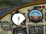
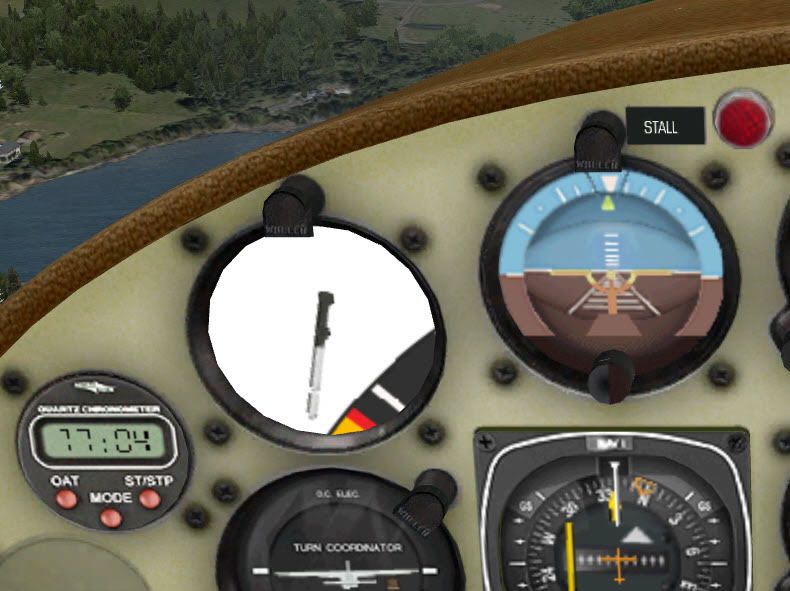
I spent some time looking at the gauges recently. If there's one thing I am reasonably good at, it's painting, but what's the point of painting a good panel and interior when the gauges still look grainy?

So I explored...

I see we can unpack the cab directories and open the many images that the "panel" uses. I see that the various panel configs define instrument size along the way, so it is obviously possible to create own images.

So I experimented...

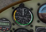
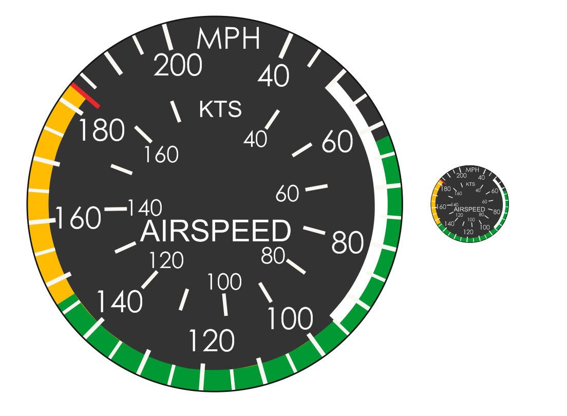
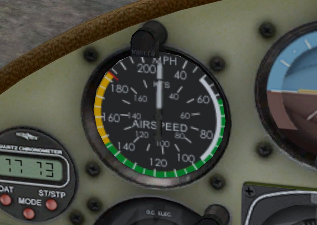
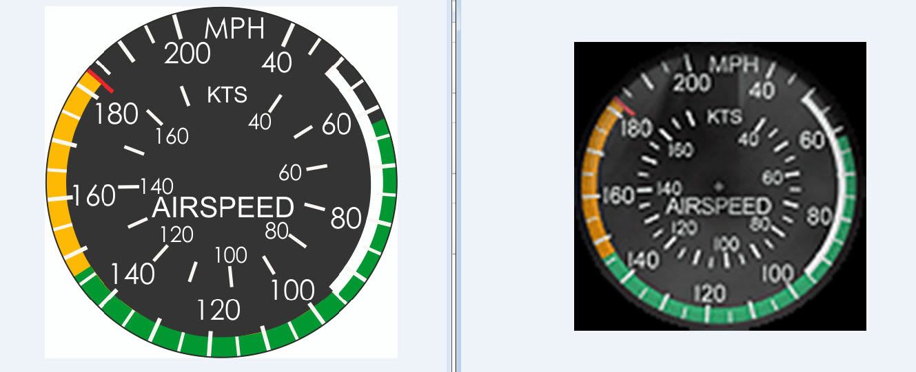
No problem - I made a really sharp ASI background image for the Maule and made the obvious mistake. The config defines the instrument size, but the large image isn't re-sized.


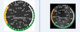
(click on thumbnail to enlarge)

Resizing the image to the config definition naturally reduces the bitmap and leaves as grainy an ASI background as the original.

Questions:

Am I missing something? Such as: do I have to use a different bmp compression? DXTbmp seems to resize the gauge bitmaps to suit itself, so I simply save the bitmap normally.

How do people like reality XP and Realair get their crisp gauges if the panel configs say the dial is x by y pixels?
 
Hi Chris,

[VCockpit01]
size_mm=512,512
pixel_size=512,512

texture=$C172s_1
background_color=0,0,0

Not certain which of the both actually does it since it's ages ago that I played with 2d gauges in a VC,
but at least one of those values sets pixel resolution of the VC's projection screen.
Up those values to 1024x1024 and your gauges should become crisper.

RealAir uses 3d gauges that are independent from the panel config file.
The gauges and their textures are loaded directly from the mdl, bypassing the limitations of the panel config.
What you see referenced in their panel.cfg's are mostly invisible gauges that provide functionality only.
 
Last edited:
I am not looking at 2D panels at all - they don't exist for me ;)

I am just specifically curious about getting the FSX VC panel to show higher detail by taking my (for instance) 512 square gauge background texture and using it in the model the same way the external textures can be displayed from 4096 pixel square texture sheets.

That way zooming in on the gauge would retain sharpness.

No panic either way at the moment anyway. I am just curious to learn something new for the "back shelf"
 
Yes, talking VC here, too, but apparently your using 2d gauges in the VC that are referenced by the panel config file, do I get that right?
If so look into the panel configs virtual cockpit section and increase the resolution. :-)
 
Last edited:
You would need to rework the XML script for the airspeed gauge to account for the larger background image.

For example, the needle's pivot point is relative to the original background image's size, so the x,y values need to be recalculated. Also, the needle's image would have to be increased in the same proportion as the new background image.

In the end though, you might not achieve your desired goal, because you'd still be projecting a large image in a small space.

As stated previously, step one would be to increase the projection screen's relative size.

[VCockpit01]
size_mm=1024,1024
pixel_size=1024,1024
texture=$C172s_1
background_color=0,0,0
 
If you can edit the *model* as well as the panel there's a crucial technique that is poorly understood but allows you to have gauges of high resolution.

(1) this is the usual method which results in low-res gauges:
* create a 3D cockpit with a texture for the panel with a resolution of say 1024x1024
* place all your gauges on it. Typically a gauge will get a 100x100 patch on the panel - it doesn't matter if you gauge background is 1000x1000, FSX will render it back down to 100x100 on the panel, not matter how much you zoom in.

(2) here's the method that gives you hi-res gauges:
* create 3D cockpit as before, place low-res gauges on the panel where that's ok
* where a gauge needs higher resolution, add a NEW PANEL TEXTURE in the model, just covering the area the high-res gauge is going to go. You don't want an actual image showing on this surface, just let it transparently show the panel behind it.
* in your 'panel.cfg' create a NEW VCOCKPIT SECTION referencing this surface in the model with a pixel_size of say 1024x1024.
* now you have an area on your panel where a gauge can sit with a higher resolution than the overall panel. Place your high-res gauge in this vcockpit section.

You could have the same effect (if FSX allowed it) by creating your main panel with a resolution 10000x10000 but of course that would lead to problems - in this technique (henceforth to be called the 'B21 technique') you have a main panel of 1024x1024 with overlaying gauge-sized areas of 1024x1024 - just do this for the special gauges.

An aircraft that uses this technique is the ASH25:
http://carrier.csi.cam.ac.uk/forsterlewis/soaring/sim/fsx/simobjects/ASH25V8/

as you will see if you zoom in to the computer vario on the 'B21 panel'. The hi-res area of the panel actually covers the computer vario and the two switches to the left of it.

b21_panel.png


Here's a 'zoom in' to the gauge in question:
302.png


Not brilliant graphics but the techique works...

edit: hey now I look at it I remember adding that rotating shadow under the gauge needle - haven't see that anywhere else.
B21
 
Last edited:
Fascinating food for thought there! And there's me thinking it'd be like the aircraft exterior textures where high resolution sheets allow you to zoom in further with better detail.

I must go give this thought...
 
- in this technique (henceforth to be called the 'B21 technique')

Very nice looking model! You are of course free to call it anything you like, but I "named" this the cookie-cutter method about twelve years ago... :duck:

The name of course comes from the "gauge shaped and sized polygons" on which the gauges are projected.

Imagine rolling out cookie dough into a 1024x1024 square pan, then cutting out gauge-shaped cookies from the dough, then rearranging them in a new 1024x1024 pan with minimum wastage of empty space.

Where the analogy fails of course is that you can't really increase the size of the cut out dough, but you can easily increase the size of the polygon cookies when arranging the mesh in the UVW Editor! ;)
 
Nice try Bill but that answer wasn't in your earlier reply...

B21

What does my earlier reply have to do with anything? Actually, looking back I see it hasn't been quite that long. I first called the technique the "cookie-cutter method" on May 4, 2004, not quite six years... :stirthepo
 
Back
Top