• Which the release of FS2020 we see an explosition of activity on the forun and of course we are very happy to see this. But having all questions about FS2020 in one forum becomes a bit messy. So therefore we would like to ask you all to use the following guidelines when posting your questions:

    • Tag FS2020 specific questions with the MSFS2020 tag.
    • Questions about making 3D assets can be posted in the 3D asset design forum. Either post them in the subforum of the modelling tool you use or in the general forum if they are general.
    • Questions about aircraft design can be posted in the Aircraft design forum
    • Questions about airport design can be posted in the FS2020 airport design forum. Once airport development tools have been updated for FS2020 you can post tool speciifc questions in the subforums of those tools as well of course.
    • Questions about terrain design can be posted in the FS2020 terrain design forum.
    • Questions about SimConnect can be posted in the SimConnect forum.

    Any other question that is not specific to an aspect of development or tool can be posted in the General chat forum.

    By following these guidelines we make sure that the forums remain easy to read for everybody and also that the right people can find your post to answer it.

GMAX Taxiways

Messages
13
Hey Guys

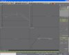
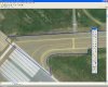
Well, I've succesfully managed to lay a high resolution aerial image into my scenery project, now I want to layer on taxiways and ramps.

My question is what is the best way to do this in GMAX? I find that my aerial photo is not detailed enough in the GMAX preview to work from.

My method so far in GMAX has been drawing lines and then converting them to an editable mesh to apply the conrete texture.

I would be curious to know what methods you guys use.

I apprecaite all your responces in advance
TED320
 
Hi,

Yes, that is the same approach I use:

  1. Create the aprons and taxiways as lines
  2. Add a cap holes modifier to them
  3. Map the texture on it as needed

I don't collapse the stack to editable mesh for these poylgons, because I want to be able to add new points to the line later on. And if you don't collapse that works fine.

After that I export these polygons with the Fs2002 gamepack (exporting only the ones I want on the same layer) and then tweaking the ASM file to get the correct LayerCall (ADDCAT) value for them, so that they display properly layered on the photo.
 
Thanks for the advice Arno!!

Maybe someone can help me with another problem I am having... I have drawn a series of lines and arcs in GMAX around my aprons/taxiways. I now want to join them together so I can put a cap holes modifier on and apply my concrete texture.

This is what I have. How can I merge these to vertexes into 1?
 

Attachments

  • gmax.gif
    gmax.gif
    36.2 KB · Views: 848
  • gmax1.gif
    gmax1.gif
    34.1 KB · Views: 811
Hmmm... I had tried this but the vertexes don't join. Maybe I am doing something wrong, I start by selecting both lines and then choose spline modifier from the drop down menu. Then I select the vertexes and hit weld.

Please forgive my lack of knowledge, I am new to GMAX!! I am trying to write a tutorial as I go along.

TED320
 
Hi

If all your lines are seperate, select one of them and covert it to a editable spline (if you havent done so already), then in the selection rollout click ATTACH. Now in any of the viewports, click each of the lines you want to attach together.

Now all the lines are attached together, doing this however doesnt join the vertex points together.

To weld the points together, enter Vertex mode and in a veiwport drag a selection box over the points to be joined (this is to make sure you select both points, I think you can also select all point to be joined), Now click weld in the selection rollout, this will weld the two points together or all if you select every point.

Note: make sure the points to be welded are close or on top of each other before selecting weld.

Hope that helps and works, I done it from memory :confused:

Stevo ;)
 
Hmmm... I had tried this but the vertexes don't join. Maybe I am doing something wrong, I start by selecting both lines and then choose spline modifier from the drop down menu. Then I select the vertexes and hit weld.

Please forgive my lack of knowledge, I am new to GMAX!! I am trying to write a tutorial as I go along.

TED320

Next to the weld option there is a threshold spinner. Increase that & it will weld both the selected points. The reason its not working now is because the points are too far apart.
 
Great guys.. Thanks for your replies.

Is it best to draw all the taxiways in gmax and export them in 1 bgl file, or divide them accross several bgl's? Also, if I have a long taxiway (or runway), should I divide it into segments rather than just having one long poly?

My work is progressing nicely, I have managed to lay a transparent concrete texture ontop of my background image, although there is a lot of overlap at the edges.

TED320
 
One BGL is fine. Its not a bad idea to have a few subDs along a large poly. I know on a PS2 console, abig long single poly will render slower than a few smaller ones. I doubt it'll make a notable diff in FS but its might help prevent clipping.
 
Hi Ted,

Splitting it in multiple BGL files only makes sense if you draw them in different GMax scenes each with their own reference point. If you export them from the same scene (with export selected) into multiple BGL files it does not really have an advantage, as they are all using the same reference point (the 0,0 point in GMax).

So it makes only sense if you design all the polygons around their own reference point, but that makes it quite hard to align them correctly to each other later on. So I would say use one file, unless the performance is so bad that you need to be able to control the v1 of the different polygons seperately.
 
New way of drawing taxiways

Hey Guys!!

Thanks for the replies. I have found a new and considerbly easier way of drawing taxiways.

I start by drawing the outlines in fireworks (i'm sure it will also work in photoshop) which is a pleasure compared to gmax. It also means I can zoom in on my high res background image for accurate placment of the points.

Next, I save the lines as a .png file and use this little convertor I found (www.img2cad.com) to convert it to a DXF file. Then, I import the DXF file to GMAX and scale it apporpirately.

Add a cap holes modifier, apply a concrete texture and voila!!

TED320
 

Attachments

  • shot2-1.jpg
    shot2-1.jpg
    66.2 KB · Views: 779
  • SHOT1-2.jpg
    SHOT1-2.jpg
    84.8 KB · Views: 830
I liked this tip and tried it out. I am running into a problem and I'm not sure how to fix it...

I am using AutoCAD to draw the lines, actually tracing right over a scaled image of the airport. I save the drawing of each component (runways in one file, taxiways in another...etc.) I open up the runway drawing and export to a DXF.

I load Gmax and Import the DXF...

I am not sure if it needs to be imported by Layer, Color or Entity....I choose Entity. The runway image comes in a an Editable Spline. Is this right? If I change it to Editable MEsh, the object disappears...

If I choose Cap Holes, my image disappears....so I skip that step. I drew the runways as polygons in Autocad so they are automatically closed BEFORE I import them...does Cap Hols still apply? and why does my object disappear when I hit Cap Holes?

What am I doing wrong?
 
I think you should convert it to a editable spline and weld the points together so its connected then use the cape holes modifyer.
 
I think you should convert it to a editable spline and weld the points together so its connected then use the cape holes modifyer.

Ok, I Import the DXF and it comes in like this...
dxfimport.jpg


The content of the DXF is already an Editable Spline, just one spline for the whole thing, <does this act as a polygon?? I was assuming it was going to....>

To get to Weld, I need to selece Vertex under Editable Spline. When I slect Weld, I get a message at the bottom of the screen that says No Valid vertices selected.

:confused: :confused:
 
Hmm try selecting a vertex then hitting the weld button. I remember i had the same problem and it was solved by doing this. If it doesnt work add me on msn ridz2018@hotmail.com and ill explain it alot better.

I attached a picture showing what to do sorry your pic isnt clear enough.
 
Last edited:
When I select the Weld command and set the spinner to a low number, it doesnt find any vertices....

If I set it to, say 10000m, it finds several and welds them, but then changes the shape of the polygon.

<trying to set up MSN now>
 
Hi,

I think it is normal that they get imported as lines. But you need to convert them to a polygon somehow. Maybe it works to just convert it to editable mesh, but else you need to use the cap holes modifier to make sure the holes (so the area between your lines) get filled.
 
Its cool arno i told him how to do it. It was that he had to connect the 2 veritces together so its a whole object then add the cape holes.
And obviously i lernt that all thanks to fsdeveloper lol.
 
Back
Top