
• Which the release of FS2020 we see an explosition of activity on the forun and of course we are very happy to see this. But having all questions about FS2020 in one forum becomes a bit messy. So therefore we would like to ask you all to use the following guidelines when posting your questions:

    • Tag FS2020 specific questions with the MSFS2020 tag.
    • Questions about making 3D assets can be posted in the 3D asset design forum. Either post them in the subforum of the modelling tool you use or in the general forum if they are general.
    • Questions about aircraft design can be posted in the Aircraft design forum
    • Questions about airport design can be posted in the FS2020 airport design forum. Once airport development tools have been updated for FS2020 you can post tool speciifc questions in the subforums of those tools as well of course.
    • Questions about terrain design can be posted in the FS2020 terrain design forum.
    • Questions about SimConnect can be posted in the SimConnect forum.

    Any other question that is not specific to an aspect of development or tool can be posted in the General chat forum.

    By following these guidelines we make sure that the forums remain easy to read for everybody and also that the right people can find your post to answer it.

MSFS20 You can never trust a Microsoft SDK

Messages
1,126
Country
australia
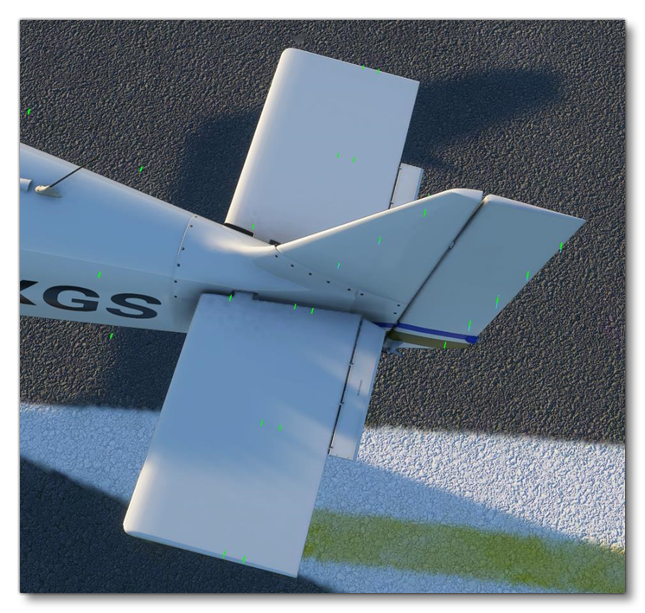
Looking at the example pictures in the MSFS SDK for defining a flight model you can see that the pictures for the vertical and horizontal tails show the aerodynamic forces in the middle of each surface.
define_fm_horztail.png


Looking at some of the default aircraft shows a different story. You can see that in these cases the green forces markers are aligned with the leading edges (just like you'd expect as the wings do the same thing).
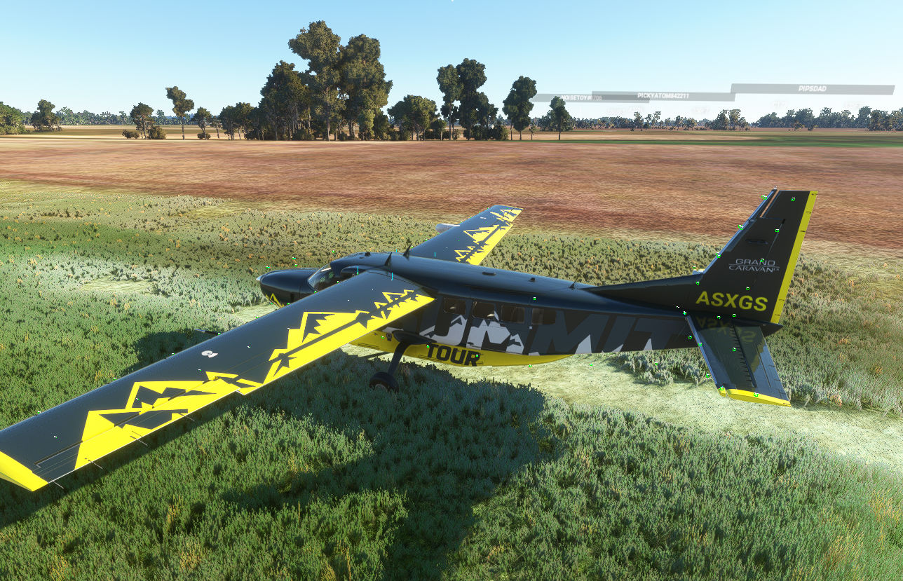
Image1.jpg


Do you expect that is because of a simple difference between the 3D model and the flight model, or are you suspicious of something more complicated going on? For most of my time working with FSX and MSFS flight models I've assumed the 'model each plate according to its orientation in the airflow and add up the effects' design, with MSFS keeping the FSX basic design (which I would be pretty sure they already regret) but dividing the plane up into a lot more plates. In each case with the force being assumed at the center of the plate (I don't have evidence for this, just an accumulated belief over many years). FSX/MSFS uses 'moment' parameters to simulate the effects of surfaces that need that, rather than altering the position of the basic force within that surface area, which adds to my 'forces centered on the plates' assumption. Because the rudder (and other control surfaces) are modelled with moments, I'm a bit dubious that MSFS knows or cares where those are at all.

Two disclaimers: all the above could be rubbish, and I'm assuming your post is raising questions for the MSFS/SDK, not the aerodynamics of a real aircraft.
 
Well, the green markers are placed based on the coordinates you enter. So the leading edge of the tail fin lines up exactly with those coordinates if you enter them for the position of the tail fin. Which is how I've always assumed FSX handles it. For example, in the top photo to get those green markers lined up like that you would have to enter a steeper sweep angle than the real value.

The problem is the SDK, https://docs.flightsimulator.com/html/Samples_And_Tutorials/Tutorials/Defining_A_Flight_Model.htm . If you look at the examples and where the green markers are then you might think that they line up with where the forces are because that's what it looks like in the pictures. But, if you look at the default aircraft (I loaded and checked about 5 or 6 of them, I only posted the Caravan as an example) the green markers in each aircraft are all aligned with the leading edges.

The SDK itself says "you should have the front line for the wing surfaces aligned with the leading edge of the wing, and the rear line of the wing surfaces at the middle of the wing. This way, the sum of the aerodynamics forces will be aligned at 25% MAC." and the example picture for the wing shows that. The Caravan picture I posted also shows the green markers aligned with the leading edges and the rear line in the middle of the surfaces.

It's just the example pictures in the SDK (top pic I posted) for the vertical and horizontal tail don't line up which could lead to some confusion.

What I think has happened is the example pictures in the SDK were taken very early on (they appear to be of some of the sample aircraft models too) and the parameters probably weren't entered correctly yet and simply, no one has updated the SDK.
 
Continuing on with this theme:

Never put

lift_coef_aoa_table = -3.15:0, -0.8:-1.029, 0:0.257, 0.26:1.5416, 3.15:0

into your flight_model.cfg file. This line comes from the SDK (Defining a Flight Model) and the SDK says it's the minimum you need for the lift table. What it doesn't tell you is that this will lead to an immediate CTD (this will happen a few seconds after the dev menu appears if you are loading from scratch. Immediate CTD if you edit the file and resync whilst in the airplane editor).

At least the other example works:

lift_coef_aoa_table = -3.15:0, -0.8:-1.029, -0.4:-0.789, -0.2:-0.572, -0.1:-0.375, 0:0.257, 0.2:1.408, 0.23:1.474, 0.26:1.5416, 0.29:1.528, 0.31:1.466, 0.4:0.842, 0.8:1.046, 3.15:0
 
lol I've just worked out the 'theme' of this thread is errors in the SDK docs. How long is this thread going to be?
 
But sometimes the SDK has some useful information:

  • ParticlePosition​

    Clicking this button will add the particle Position property to the block, which defines the position where the particle will be initially created relative to the emitter (in meters).
    IMPORTANT! Currently the orientation of the axis for the position is based on the world axis. This means that - for example - defining a y axis position of 5 meters will spawn the particle five meters from the emitter, but the actual position is not along the local y axis of the emitter, but rather the y axis of the world. If the emitter is at the north pole then the particle would be emitted "above" the emitter, but if the aircraft is at the equator then it would be emitted to the "side" of the emitter. This is true for all three axis. This is something that will be changed in the future.
Now, the real question is why the hell does the ParticlePosition use the world axis? I was making an FX and tried fine tuning the particle position but I couldn't figure out why changing one value was moving the FX up, forward and sideways at the same time. But after reading this it makes perfect sense. The x,y,z position is based on the world axis which is, without a doubt, the most useless thing I have seen in a long time. Unless you need an FX that is 5 metres above the ground at the north pole but 5 metres to the side at the equator.

Quick tip, when using the Visual Effects in game, stop (and maybe remove) any effects that you may have spawned and that you have running before switching to another effect. Otherwise it's straight to the desktop you go (ie CTD). Save your progress often.
 
Hmmm. So how do you implement cockpit lighting?

I'm working with the new Visual Effects editor to create engine start smoke and dirt/grass/water wheel effects and not using the old legacy style effects. As far as I can tell at the moment Lights are not supported in the new Visual Effects. It seems you have to use legacy effects for lights.

For example, you attach new Visual Effects with Model Behaviors and reference them by GUID. With Lights you use the system.cfg file and reference them with the .fx filename just like in the good old days. The ASOBO A320 is probably the most comprehensive example of the new FX. You can see them in the A320_NEO_FX.xml in the model folder but they only use this for contrails and landing wheel fx.

My plane doesn't have any lights so it's not something I have to deal with yet.
 
Anthony,

If you are studing the Visual Effects Editor, do you read this: https://devsupport.flightsimulator.com/articles/2809/su6-changes-you-must-make-on-your-fxs.html

It seems that there will be profound changes in this tool from SU6. In this topic, advices can be found to manually modify the contents of effects xml files in order to be compliant with the next version of this tool.
Thanks Didier

So what you're saying is, that what is written in the SDK about visual effects shouldn't be trusted because it's going to change in the next update?

Does anyone else get the feeling it's two steps forward and one step back developing for MSFS? I swear, I spend 50% of my time trying to resolve some sort of bug or issue with MSFS instead of actually developing.
 
Yes,
This information from Q&A Offcial forum seems to be written by a member of Asobo Team ... so ...
 
Last edited:
textureThis is the material ID of the screen where the instrument will be drawn.

IMPORTANT! Previously - in FSX - this string needed to be preceeded with a $ sign. However in Microsoft Flight Simulator this should not be used as it is now used to indicate to the engine that the material is a collision material, which is obviously not the case for gauges.

Why do you lie Asobo?

Yeah, I tried using a plain material ID (because the SDK said "this should not be used") but my gauges would not appear. Only when it was preceded by a $ sign would the gauges appear, just like it does in all the default aircraft. Yes, I changed the material in the model and in the panel.cfg.
 
  • Like
Reactions: tml
What I think: the writing of the SDK is outsourced to an external company and Asobo faithful to its policy of testing before delivery does not check (waste of time = costs) and many gross errors fall through the net.

A correct quality service worthy of this nm would allow to solve a good number of errors but at the price of a slight financial surcharge. In the long run this would be profitable for them.
 
Not to mention https://docs.flightsimulator.com/html/Samples_And_Tutorials/Tutorials/Defining_A_Flight_Model.htm bestessays has images of two different aircraft for the sample project, and the numbers for tuning it are all over the shop.
Worst tutorial ever, if you can't trust the information.
Something is wrong with the cache for installer msi files for my sdk installations, but I have no idea how to fix it. When I attempt to install the SDK, it always hangs. I've tried using the windows force uninstall troubleshoot utility thing, but that doesn't resolve it. I've attached my logs from an install attempt.

College coding homework help takes a normal of 80 to 240 minutes. The tasks demand different time periods relying upon intricacy, size, a student's dominance of ideas, and arranging. Fledgling students learning essential thoughts of programming or a particular language get some margin to finish even the easiest coding errands, while those with experience are a digit quicker.
 
Last edited:
Maybe I'm not understanding something about this bit in engines.cfg about propellers:

prop_mod_use_absorbed_torque

When set to 1 (TRUE), this parameter permits you to partially switch to the modern prop simulation but not feed back the modern absorbed torque value into the engine system.

Default value is 0 (FALSE).


This is wrong isn't it?

I have been spending the past week trying to get the modern propeller model to work. Specifically for my aircraft there is enough power absorbed at idle that setting the MP to field pressure (ie 29.92inHG) should give 1950-2100RPM. I have been completely unable to do this with the modern model so I switched to the old version and used the prop_efficiency_table and prop_power_cf tables and had it working in no time.

So I just went back in to see if I could use the prop_mod_use_absorbed_torque value to use the old tables while using the modern propeller model. Unless I am very mistaken setting:

prop_mod_use_modern = 1
prop_mod_use_absorbed_torque = 0
prop_uselegacytables = 1

will use the modern propeller but the old prop_power_cf table.

If you want to use the modern propeller and modern absorbed torque values then you actually need to set:

prop_mod_use_modern = 1
prop_mod_use_absorbed_torque = 1

and prop_uselegacytables becomes irrelevant.

And isn't that different to the description in the SDK? According to the SDK setting prop_mod_use_absorbed_torque = 1 means you are not feeding back the modern absorbed torque value. Funnily enough "prop_mod_use_absorbed_torque = 1" itself suggests that it you are using the modern absorbed torque values.
 
Back
Top