Hi Misho:
IIUC, you refer to the workflow cited in MSFS SDK Docs'
SimpleAerial sample:
https://docs.flightsimulator.com/html/Samples_And_Tutorials/Samples/SimpleAerial.htm?rhhlterm=Aerial
"
SimpleAerial
The SimpleAerial sample illustrates the process of creating a new package of aerial images to blend in with aerial imagery already in Microsoft Flight Simulator. Creating aerial image add-ons uses a combination of *.PNG files for the images and *.XML files to tell the game how to render the images. Note that images are not stored in the game as PNGs, but rather uses the propriety
CGL file format, which requires defining in the XML for the package.
You can expand the link below to see the SimpleAerial file and folder structure:
File Overview
Code:
|---+ SimpleAerial
     |---+ PackageDefinitions
     |   |---- mycompany-aerial.xml
     |---+ PackageSources
     |   |---+ CGL
     |       |---+ aerial_images
     |       |   |---- 02123020101020302010.png
     |       |   |---- 02123020101020302011.png
     |       |   |---- 02123020101020302012.png
     |       |   |---- 02123020101020302013.png
     |       |   |---- 02123020101020302101.png
     |       |   |---- 02123020101020302110.png
     |       |---- my-cgl-info.xml
     |---- SimpleAerialProject.xml
Aerial Image Format
Aerial image files are created at the highest level of detail,
LOD20:
| Level of Detail | Map Width and Height (pixels) | Ground Resolution (meters / pixel) | Map Scale
(at 96 dpi) |
|---|
| 20 | 268,435,456 | 0.1493 | 1 : 564.25 |
NOTE: You can find full details of the different LOD values as well as other things related to how map tiles are calculated
here.
All image files for aerial images should be authored as
16-bit PNG with a fixed size of 256x256px, and the build process will automatically generate the images for the lower levels of detail. Note that the
alpha channel of the provided aerial image PNG is used to blend between the image and the in-game aerial, where a pixel with alpha 0 means the in-game aerial pixel is used, and 1 means the provided aerial pixel is used. Any value in-between will create a linear interpolation between the in-game aerial and the provided aerial."
IIRC, FS2Kx required an Alpha channel
and min. LOD-13 imagery to prevent fall-back to default land class display.
MSFS now requires use of Alpha channel and min. LOD-20 imagery to prevent fall-back to default 'land class' display (Bing imagery and/or projected mesh objects).
PS: I am curious if editing the gray scale value of a custom source Alpha channel eliminates display of a "detail texture"
blended with MSFS' default
in-game aerial ?
FS2Kx used a total of 256, 8-Bit gray scale values in the "Blend" channel.
MSFS SDK Docs seem to infer that it calls for use of "fractional" numeric gray scale values between 0 and 1 in the Alpha channel to enable
blending.

Is Asobo equating Alpha channel values of
0 with Pure Black and
1 as Pure White (aka a value of "255" in FS2Kx) ?

[
EDITED]
AFAIK, Alpha channel values of
0 with Pure Black and
1 as Pure White (aka a value of "255" in FS2Kx)
without "fractional" numeric gray scale values between 0 and 1 in the Alpha channel are used to enable either Water ('Hydro' surface attributes) or Land respectively, and thus define a 'Water-Land Mask' in the FS2Kx Resample SDK.
Can anyone here confirm that MSFS SDK has implemented a custom photo-real definition mechanism that now works 'Asobo-Backwards' (aka "As$-Backwards" ) ?

I am not seeing sufficient 'detail' to explain the process in this Asobo Terrain Development slide show:
BTW: "Some" info on Detail Maps with MSFS default aerial imagery can be seen on Pages 84-90 in the above PDF.

One may wonder if "
custom detail maps" can be used for more 'perceived detail' with "
custom Aerial Imagery" at run time ?

If not, IIUC, one must otherwise use 3D glTF PBR textured
TIN G-Poly (Sim-)Objects (...that require Z-Buffer Fighting mitigation) ?
 https://en.wikipedia.org/wiki/Triangulated_irregular_network
https://en.wikipedia.org/wiki/Tessellation
https://en.wikipedia.org/wiki/Triangulated_irregular_network
https://en.wikipedia.org/wiki/Tessellation
AFAIK, this is distinct from "Projected Mesh"; MSFS SDK Docs says 'that' is rendered on ground in 2D at
default texture resolution:
https://docs.flightsimulator.com/html/Introduction/Introduction.htm?rhsearch=Projected Mesh
"
IMPORTANT! When being rendered,
projected meshes are baked into the terrain textures. This helps reduce the polycount and permits the element to be terraformed. However, it also means that
the texture quality won't be any greater than the resolution of the terrain textures themselves. In general, this resolution is around 4cm/pixel at the equator, with the best/highest resolution terrain textures reserved for higher LODs so we have a better quality for airports. For users, they will experience the best resolution possible setting the "Terrain level of detail" option to its maximum value."
Regardless, 4cm (3.75 cm aka "LOD-20") is already a very high resolution.
Historically, very few
custom- and no default- 3D models for FS used a 2cm (1.875 cm aka "LOD-21") or greater texture resolution.
https://www.fsdeveloper.com/forum/threads/flattens.425495/post-633002
Some practical considerations:
https://www.fsdeveloper.com/forum/threads/airport-ground-poly-that-follows-msfs-dem-model.451670/
Who can / will post here, a worked "
Proof of Concept" that is a
true 3D model MSFS glTF (Sim-)Object '
TIN ' G-Poly ?
https://www.fsdeveloper.com/forum/threads/msfs-projected-mesh-looks-ugly.450563/
UPDATE: Dick had already posted a 'worked example"
true 3D model MSFS glTF (Sim-)Object '
flat ' G-Poly ...in this thread:
 https://www.fsdeveloper.com/forum/threads/custom-markings-using-projected-mesh.454932/
PS
https://www.fsdeveloper.com/forum/threads/custom-markings-using-projected-mesh.454932/
PS:
Pete Beeby's perspective on this issue of Detail Maps with MSFS default versus custom aerial imagery:
.......@Risuali45,
Regarding your issue, I have looked into it closely and have decided not to pursue projected mesh ground polygons because of it.
I have been designing hi-res ground textures for years and am proficient in the required material properties for importing into FS2020, but in my view the end result is not satisfactory when using the ProjectedMesh technique.
As you say, when projected, the texture is “diluted” by the default “Detail” texture used by the Sims engine, selecting a different material type only changes the appearance slightly, but your custom ground texture will still have this washed out “Asphalt” look bleeding through.
There appears to be no setting that is able to turn the default “Detail” texture off.
I have noticed that when using XML for the creation of Airport Surfaces, along with the “DrawSurface=True” parameter, there is a “DrawDetail=True” parameter.
I am presuming this refers to adding the default surface type “Detail” material to the Texture.
I have found that even if you change the parameter to “DrawDetail=False” it makes no difference to what the chosen hard surface will look like in the Sim.
Asobo need to include a “Detail” map which can be aligned to a Surface Material, without it having any visual detail, ie blank.
In FSX, I seem to remember, they used two default “Detail” ground texture and if you used an enhancement package like REX for example, REX would replace those for “Blank Detail” textures so that the default detail would not interfere with their replacement ground textures.
In Short, we need Asobo to address this.
Here is Asobo's reply on Dec 15 2021, to yet another report on the issue of Detail Maps:
https://web.archive.org/web/2022051...-rid-of-surface-type-detail-map-textures.html
By comparison, here is related info on
FS2Kx Terrain Design Procedures:
Some pertinent info:
 ACES' FSX Global Terrain expert Adam Szofran said
:
https://www.avsim.com/forums/topic/...-default-water/?do=findComment&comment=558800
"With the FS9 Resample tool, the water mask punched a hole in your image to reveal default water beneath.
With the FSX Resample tool, we wanted to allow more flexibility, so we changed how the water mask works and we also added a blend mask. Now the water mask triggers reflective and specular water effects, but it doesn't punch a hole in your image. The benefit of this is that you can now paint the water any color you want. For example, if your source imagery contains murky brown swamp water, you can now get the muck to show up in FSX with reflections and specular effects. If you'd rather just see the default water colors, you have to use a blend mask to punch a hole in your image to reveal the default textures below. Note, however, that
the default textures revealed by the blend mask might not be water; they could very well be land textures! Therefore, if you want to guarantee that the blend mask will expose default water textures, you need to create a water polygon (a big square one will do) that covers the area where you want water to appear. For information about creating water polygons, look for the documentation of the shp2vec tool in the FSX SDK.
Good luck,
Adam"
Szofran, A. et al., "Microsoft ESP: Global terrain technology for Microsoft ESP," Jan. 2008, 22 pages
https://web.archive.org/web/2010102...FSInsider/developers/Pages/GlobalTerrain.aspx
https://web.archive.org/web/2010102...539214f2e/GDC2006_Szofran_Adam_Terrain_v1.doc
https://web.archive.org/web/2011082...2d7f6a45b36e/GDC2006_Szofran_Adam_Terrain.ppt
https://online.fliphtml5.com/yyld/cvaw/#p=1
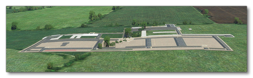
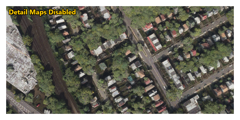
PS: For a quick preview of what local scenery looks like with the
Detail Map overlay disabled,
MSFS SDK Docs explain this in
Options:
https://docs.flightsimulator.com/html/Developer_Mode/Menus/Options.htm?rhhlterm=detail details maps&rhsearch=Detail Map
"Detail Maps: When enabled, detail maps will be added to the terrain to increase fidelity. Disabling this removes these maps. Mouse over the image below to see the difference (this option is on by default)."
[
END_EDIT]
GaryGB


")


